(or how we went from Paper to Powder to Part…)
Side Note: This work was also featured as the keynote article in the July 2017 issue of NAFEMS Benchmark.
Additive manufactured parts are everywhere – from Aircraft engine fuel nozzles to dental implants to mountain bike thingamajigs. It’s seems like there’s no barrier to what can be made, with the only restriction being the engineer or designer’s imagination. Yes, the current set-up and manufacturing costs can often be eye-wateringly high, but the continual development of new machines and processes will bring those costs down. We’re not so far from the point where companies can expect to produce ground-breaking parts, and still manage to pay for the doughnuts on a Friday.
Polymer-based machines, using FDM-type processes, have been around for some time now, and we’re starting to see real product innovation. The application of qualified engineering materials such as the Stratasys Ultem material family and even Carbon-Fibre (albeit, short-strand) printing allows designers to create prototype and short-run operational components at relatively low cost. A recent GrabCAD Challenge, sponsored by United Launch Alliance, used ‘crowd-designing’ to generate nearly 400 concepts – the winning design (to be manufactured in Ultem 9085) will go into outer space as part of the Atlas V rocket system, with a lower cost and weight than their legacy metallic counterparts, made using traditional ‘subtractive’ manufacturing techniques.
While printing in plastic is straightforward if you’re running your own machine, or even if you’re not and want a cheap prototype (upload an STL to Shapeways or 3D Hubs, pay your $34.76, and wait 3 days for the postman), the ease of printing in metal is a whole universe more involved. There are a multitude of barriers and considerations, both tangible and intangible in developing something that will work. Obviously, the cost is high, both in machine and materials, but also a complete change in mindset is required to produce a design that i) works, ii) is better than its ‘subtractive’ cousin (‘better’ can often be an intangible, but strength- or stiffness-to-weight is a good place to start) and iii) is cost-effective to succeed (and not be caught in the ‘it’s not really any better, but it’s AM, and people will pay more for cool’). If you then decide that your metal-based concept/project/idea is going to be better using an AM approach, then you’ll need to embark on a potentially-convoluted journey to get from your blank piece of paper to a production component.
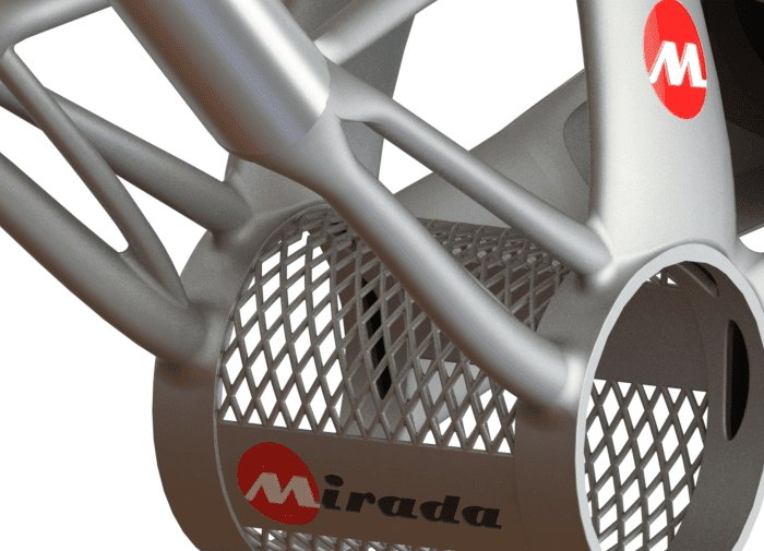
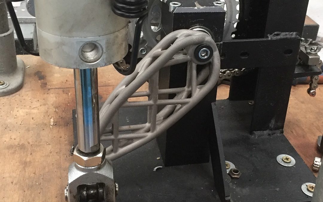
In the following paragraphs, I’ll try to cover some of the key highlights and pitfalls we (Evotech Computer-Aided Engineering Ltd) had to address when developing a metallic AM-focused component – this happened to be a road bike chain-set, but could have been anything really, provided it would fit into the machine, and we understood the operating parameters of the component during service. This work was performed in conjunction with Mirada Pro, who specialise in metallic AM, based in the UK. Mirada already had ‘Design for AM’ experience in their collaborations with people like Reynolds Tubing and Moots. This, however, was their first development project, which looked at an analysis-focused design and manufacturing strategy, complemented by rigorous product testing.
Design Optimisation (‘Don’t Believe the Hype!’)
When Public Enemy uttered those words, they were talking about ‘80s Hip Hop, but could equally have been referring to Design Optimisation. There are many companies (usually software vendors) who would like to have designers and engineers believe that their tools have the magic ‘Optimised Design for Print’ button – i.e. it doesn’t matter whether you have any clue as to what an efficient structure needs to look like (or know how to analyse one), if it’s been through our fancy ‘black box’ solver then it’ll be fine. Real design optimisation doesn’t work like that. Yes, there are tools, some simple and some hideously complex, that can help, but if the output cannot be justified using basic engineering fundamentals and load path analysis, then it’s unlikely to be optimum (two points joined by a straight line under axial load need a constant cross-section, anything else is just ‘computational guff’).
That said, there are many structures which are indeed highly-complex, in terms of potential design space, interaction with surrounding structure and multiple loading cases/environments. Of course, AM and Design Optimisation allow engineers to explore this design space to understand what is efficient and, ultimately, optimum. Therefore ‘standard’ optimisation tools are available for conceptual (topology optimisation being the most widely used) and detailed (gradient-based sizing and shape optimisation) design space exploration. Other methods are available, such as evolutionary/genetic algorithms and topometry/topography searches. The key is to use the Design Optimisation strategy as an engineering tool, and to clearly understand what the output is saying, not just blindly accept the answer as ‘computer knows best’.
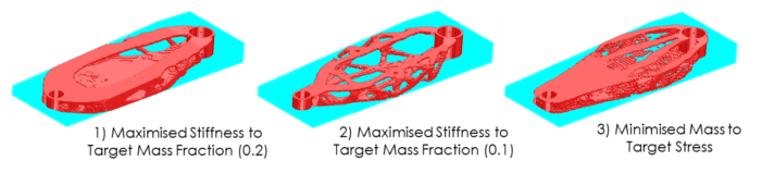
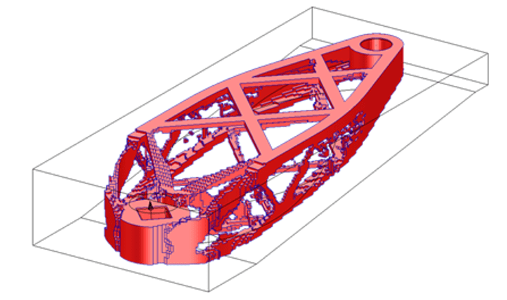
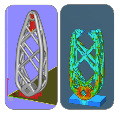
In terms of the Design Optimisation for the AM bicycle chain-set, we explored several different techniques in understanding the optimum material layout for our design space and loading scenario. One interesting aspect in the ‘blind’ use of topology optimisation (based on analysis of the 3D design space) was that we got completely (and I mean completely) different layouts depending on whether we used a minimum compliance solution (i.e. maximise stiffness for target mass), target stress (for minimum mass) or a combination of the two. In addition, we found that the design volume mesh density and the analysis parameters (such as the ‘power’ term, which influenced how much material could be removed between subsequent iterations) had a major impact on the solution time, but also in capturing the some of the key design features, often missed by too coarse a solution.
As well as the potential variation in layout, a further difficulty would have arisen in converting the ‘fuzzy’ topology optimisation output into smoothed working geometry. Given that one of the intentions of this project was to develop an optimisation strategy which could be used for a wide variety of rider inputs, such as loading and ergonomics, it would have been highly-inefficient to perform this ‘concept to detailed’ geometry conversion for every custom scenario.
Optimisation Strategy (‘The Truth is Out There’)
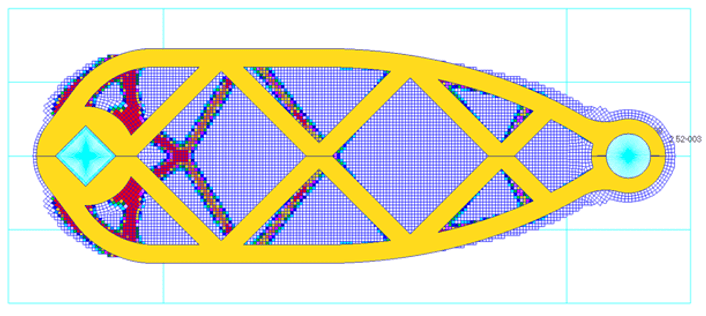
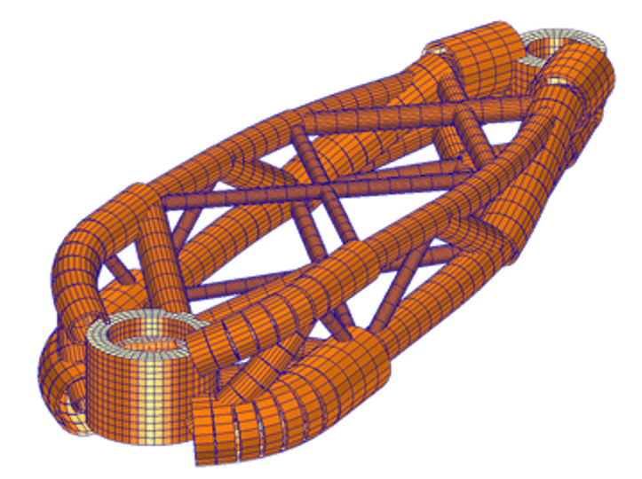
Given that the ‘blind’ 3D design space approach was problematic, we took a step back to understand the primary loading acting on the chain-set. The pedalling action was made up of a combination of in-plane (bending/axial) and out-of-plane (torsion) components. We were therefore able to first assess the in-plane loading using a two-dimensional design space. This had a major advantage; the model ran much quicker than a full 3D design volume, allowing rapid turnaround in output allowing us to tune various aspects such as symmetry and minimum member size. The variation in output seen in the 3D design space was vastly reduced in the 2D analysis, with a far better match between different analyses. In addition, a clear truss-like structure was beginning to form whose load-path was more intuitive, along with a clearer material layout. Another very important aspect of the truss-like design was in the member orientations, which would have major benefits in reducing (or even removing) the need for print support during manufacture.
Once we had converged on a feasible and efficient design from the 2D topology optimisation, the resultant ‘geometry’ was extruded into 3D ‘trussed’ design space for combined in- and out-of-plane loading. This had the major benefit of retaining the overall trussed profile, yet did not fill the overall 3D design space in areas where we knew we would have redundant material. Consequently, the trussed 3D design space would achieve a far quicker and more robust solution, than simply relying on the original ‘full’ 3D design space.
The optimised output of the 3D topology output showed clearly the influence of the in-plane (bending/axial) load with the trussed profile. The out-of-plane (torsional) load component was clearly seen in the ‘hollowing out’ of the design space to yield a 3D torsion box design. Therefore, the sequential ‘2 followed by 3D’ topology approach led to to a more sensible conceptual design, which was more appropriate for downstream sizing optimisation and printing.
Detailed Sizing Optimisation and Verification (‘It’s All in the Numbers’)
With a good definition of the conceptual design and overall material layout, the next stage involved applying real world constraints to the model, based on stress and displacement. The main loading mechanism on the chain-set was due to the cyclic action of the pedal stroke, with the ISO certification (required to allow commercial sale in Europe and the rest of the world) based largely on a fatigue test requirement of 100,000 cycles. Consequently, the driving stress constraint on the model was a limit fatigue stress governed by the fatigue characteristics of the material (Ti6Al4V in this case).
One difficult aspect was the fatigue strength qualification of the AM material. Due to the layered build process, with its stepped profile, the fatigue properties of AM materials are notoriously poor. There are several ways to alleviate these issues by either mechanical treatment of the surface to effectively machine off local imperfections (where machine providers quote ‘near net shape’ fatigue properties) or chemical treatment to perform a similar task, although with less regularity in the finished profile. However, both techniques require significant post-production treatment, and are far less effective for hollow structures (which was fundamental for the chain-set). Instead, it is far more useful to develop fatigue properties for the ‘as built’ material. This data was made available following extensive coupon testing for a sample built using similar production parameters and orientation.
This gave an allowable stress to be defined based on the target fatigue life of 100,000 cycles. Both a Maximum Principal and Von Mises Yield Stress Criterion were used as stress constraints within the detailed sizing models, given the potentially complex loading mechanism. The target stiffness was calculated based on the published performance of similar cranks, and applied as a maximum displacement constraint at the key load application points. With constraints defined, a global objective of minimum mass completed the optimisation definition.
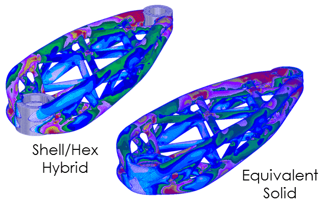
The initial detailed optimisation was based on a bar element definition, whereby centre lines were created in alignment with the layout output from the topology optimisation stage. Pedal and axle bosses were modelled as solid regions, with appropriate ties to allow full force and moment load transfer. The bar model used a series of hollow circular property regions, each defined with an outer diameter and fixed wall thickness. Property symmetry was used to ensure a mirrored design about the main axis (allowing a common left/right arm design). The optimisation was run with the constraints and objective to yield the optimum bar dimensions. The output clearly showed areas which would require internal stiffening, especially at the boss interfaces.
Once the optimum bar dimensions were understood, a second detailed sizing model was developed, based on a shell definition of the overall diameter profiles, and internal web stiffeners at the boss interfaces. This allowed a more accurate geometry, especially at the stress raising features where adjacent bars met. Again, the model was broken into a series of property regions, with a shell thickness design variable set for each region. The pedal and axle bosses were maintained using a solid definition, and ‘glued’ to the shell structure to allow full force and moment load transfer. Before any optimisation was performed, a verification model (including a uniform 1 mm shell thickness) was compared with an equivalent solid model of the same dimensions. A very good correlation was achieved, which gave confidence in the overall approach.
The final detailed optimisation (based on the gradient sizing of shell thickness) was performed using the ‘hybrid’ shell/solid model, with the existing constraints and global objective. The output showed the optimum wall thickness for minimum mass, whilst respecting stress and displacement constraints. The final optimised design showed significant benefits over a comparable metallic chain-set with the following performance improvements; 300% stronger, 340% stiffer and 100% increase in stiffness to weight ratio.
A Side Note on Lattice Structures (‘Nice Cleavage’)
Many areas of industry are heavily involved in the application of AM-generated lattice geometries to act as heat dissipation mechanisms and/or filtration. Structural examples are also being developed, as a means of supporting thin walls, or even to engineer ‘new’ materials by changing the stiffness characteristics in different directions. However, the very small features which define these lattices can lead to local stress raisers, and therefore a highly-complex stress state.
In static and dynamic impact applications, considerable safety factors are required, often negating many of the weight reduction benefits. In the case of fatigue-loading environments, the situation becomes even more uncertain. Without robust fatigue life data for these lattice structures, the overall behaviour is very difficult to quantify for use in a ‘Design for AM’ scenario. Sure, there are tool-sets out there that will quickly generate the complex mathematical forms, and even optimise the lattice member dimensions, but without reliable material data, their performance is approximate at best.
All the chain-set design optimisation work was focused on thin-walled structures, which formed either the outer skin of the hollow tubular sections, or the internal webs within the hollow sections. This was so that we could control the geometry with known fatigue data for equivalent sections, ultimately giving us confidence in the down-stream physical testing. This information for lattice structures simply wasn’t available.
Fatigue Life Optimisation for Mass Customisation (‘Marginal Gains’)
A fatigue life optimisation approach was assessed under a more complex loading environment. While the single load case ISO test was required to allow product certification, ‘real world’ loading was made up of a varying spectrum of the cyclist-applied forces at different time intervals. However, given the ubiquity of power meters within all forms of cycling, this load history could be developed for any rider. With a well-defined FEA-based optimisation approach, this load history could be used to generate a bespoke chain-set for any rider. Thus, the potential for customised design becomes a very real possibility.
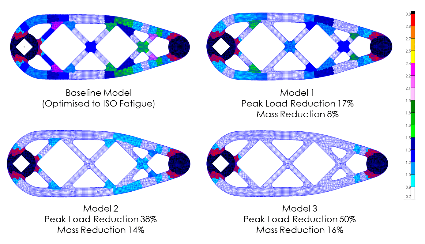
This concept was tested for several different loading profiles, for a variety of different riders. The output showed that those riders with a lower average power (load) profile, could expect a far lighter chain-set for the same target fatigue life as a much more powerful rider. For a rider with 50% of the baseline power output, the mass reduction could be as much as 16%. Potentially greater mass reduction would be possible with optimisation of the crank to axle interface (out of the scope of this project, but currently in development).
Manufacturing Simulation (‘Optimum Design, but Can We Make It?’)
So, a lot of development work went into the optimisation process, both to generate an initial chain-set design (focused on the ISO test) and, perhaps more importantly, a strategy for the generation of a customised chain-set, based on any rider’s power profile and ergonomics. That’s great, but if we can’t make the thing, then it’s all pretty much irrelevant. Of course, one of the beauties of the Additive Manufacturing process is the ability to generate shapes which would be difficult or impossible to produce using traditional means. That said, AM doesn’t have a magic wand, and does have real limitations during production.
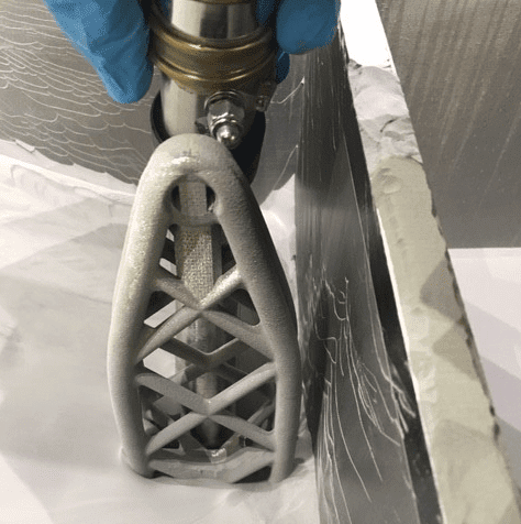
Probably one of the first considerations of the AM-focused geometry is in the support structure. The ‘overhang’ rule means that regions greater than a given angle (typically 45°, but variable based on machine and material parameters) from the vertical require additional support. Support structure can help with very complex geometry and is often used to act as a heat sink to dissipate thermal energy and minimise distortion for what is a very high temperature process. However, it adds to the total cost of the build, both as additional material and the additional post-processing to remove from the part. Consequently, for an optimum product the support structure needs careful consideration within the design.
The conceptual design of the chain-set (based on the output of 2 and 3D topology optimisation), showed a clear truss-like form. During this and the detailed design phase, the resultant geometry was subtly modified (mainly at the axle boss intersection) to respect the ‘overhang’ rule, in that all major members were less than 45° from the vertical. Thus, the requirement for support structure was minimal, and focused on small areas at the build plate interface and pedal boss. Tooling access to these regions was straight-forward to allow relatively easy removal after AM.
AM of metallic parts can be likened to a welding process, in that there are significant levels of heat required to incrementally solidify/fuse the powder and form the structure. There are many factors which influence the success of the build process, often with iterative manipulation of the physical machine parameters and part orientation.
We were fortunate to have access to a FEA-based tool-set, recently developed to model the AM process. This technology had been ‘spun out’ of a welding process modelling software, and used the ‘inherent strain’ method to predict both the distortion and residual stress levels within the part. The full analysis involved the multi-stage consideration of i) build, ii) support structure and base removal and iii) heat treatment of the finished part.
The manufacturing simulation output showed some areas of residual stress, but these were away from the critical loading points, and of much lower magnitude. Additionally, the output showed that for the thin-walled, symmetric structure (which was ‘balanced’ under thermal load), the levels of distortion were negligible.
The overall outcome of the manufacturing simulation allowed us to better understand the physical process, thus building confidence in the design and down-stream behaviour. With some machine coaxing, we could build several test parts, which well represented the design intention. Once built, the internal powder within the hollow sections was ‘drained’ thorough a hole in the threaded area of the pedal boss.
Physical Testing (‘The Proof is in the Powder’)
Testing of the finished chain-set was performed using the ISO pedal fatigue test rig at an approved test house. The original intent was to produce a design optimised to achieve 100k cycles of load, with no margin of safety (ultimately to minimise mass). The physical result demonstrated a life of 96k cycles (i.e. within 4% of the target life), thus demonstrating good levels of correlation, which are often difficult with fatigue testing. For operational components, a safety factor could be used to give a significant increase in life, with only a marginal increase in mass.
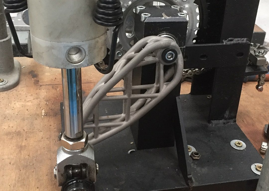
A comparison between physical test failure and optimised FEA output was performed with a very good correlation, both in terms of crack location and predicted stress to fatigue life data.
Conclusions
This work highlights some of the key development steps in the design optimisation, manufacturing simulation, production and physical testing of a complex AM-produced part. While I haven’t gone into huge amounts of detail regarding discrete numbers and tool-sets (these are available on request, though), I hope I’ve covered the main topics in a manner which brings the whole process together.
There are areas of the component design that could be improved (apologies in the following terminology for non-cyclists). One of the main constraints was that the chain-set had to function with an existing ‘square taper’ axle connection. This had two major impacts on the final design. Firstly, the standard square taper axle forms part of what is generally regarded as an outdated and heavy bottom bracket, and therefore negates some of the minimum mass design of the chain-set arms. Secondly, the discrete axle attachment didn’t allow the design space (including axle) to be explored fully. If the axle region was included in the design optimisation, and ultimately in the printed design, then a radically different concept (with further mass reduction) could have been generated.
With all that said, I hope you’ve found this article both informative, interesting and useful for any ‘Design for AM’ challenges you are embarking on. Please let us know if you’d like to continue the conversation.